|
|
|
| Ideas for Design | |
|
Here you can find electronic circuit ideas. Basic knowledge of electronics is again a prerequisite! Use an old unused mobile phone to make an inexpensive alarm activated alert. This idea was inspired to be an add on in remote alarm systems. This is where you need an alert in case you are away and the alarm goes on. Telephone lines are not always present and is the first thing burglars cut before thet break into. A mobile phone is not wire dependent and can be powered by the battery of your alarm system. Use an old mobile phone. We used an Ericsson 788 . Unscrew and reveal the keypad where you should use very thin cables to solder on the contacts of key yes and any other numeric key suitable. You needn't solder 4 wires as one joint is common. Find it with a multimetre. Take care not to short circuit the keypad. For power connect directly to battery joints as illustrated |
|
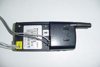 |
Preparing the mobile phone
Use a SIM card of a Network provider estimating the signal strength in the area of application (Cosmote, Vodafone, Tim, Qphone ). Enable power up without PIN required. Register in the wired key (one touch key memory) the number you wish to be called in case of alarm. In this specific mobile if you press a keypad number and then Yes the phone number stored in this memory position is called.
|
 |
How the circuit operates
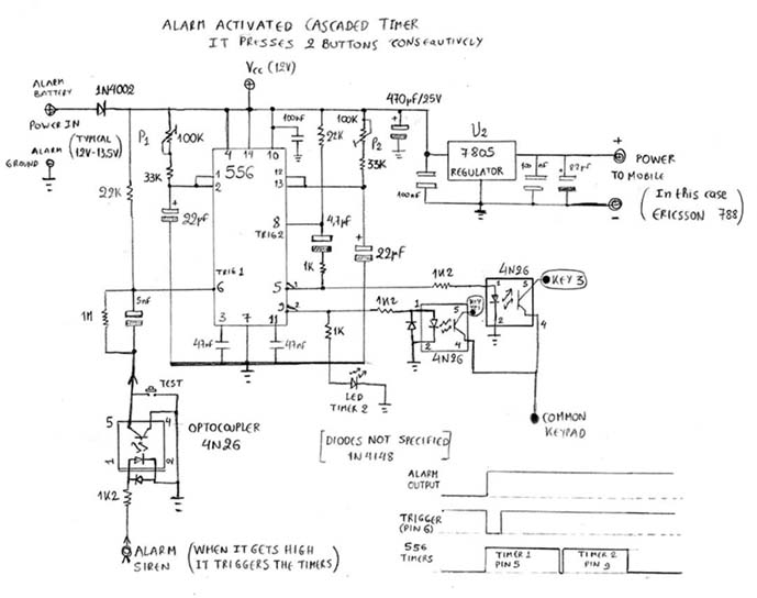
The heart of the circuit is a NE556 which is a general purpose dual bipolar timer. The circuit may be triggered on falling waveforms and the output structure can source or sink up to 200mA. In our case both timers are operated as monostable.
Power is supplied to the circuit by the alarm output which feeds the IR motion detectors and therefore it is powered even in case of power cut as battery will undertake. U2 regulates the voltage to the mobile which in our application needs around 5V.
P1 & P2 adjust the duration of the timers thus the time numeric button and confirm button (Yes, hook on) are pressed. This time shouldn’t be too long so adjust them accordingly.
I selected optocouplers 4N26 to drive the mobile buttons because in this way mobile circuit remains isolated. Relays would be too much because keypad currents are low. In the same logic an optocoupler is used to interface the alarm output to trigger the circuit.
The circuit is triggered only when the alarm output gets from low to high (this transition sets pin 6 to low for a moment). Then executes a cycle in which timer 1 starts (numeric key is pressed) and after this timer 2 follows (Yes key is pressed). As long as alarm output remains high no other cycle is executed. Led is an indication that cycle is executed properly (it turns on when timer2 counts). |
 |
Implementing the circuit
Using a mobile in this way you simply have an inexpensive alert application. Bear in mind that there is not duplex communication between mobile and circuit so you cannot ensure that network is available or the unique number called is busy or switched off. Moreover, if the mobile display is not in its initial menu there is no guarantee that by pressing these buttons you can call the other party. For professional applications of this type visit |